
NGA Next-Generation Audio Standard
Describe sound as spatial objects and connect rendering to the actual loudspeaker layout.
Explore Next-Generation Audio
Core Technology
SAP 7100X
Scroll from incoming samples to weighted mixing, filtering and time alignment — then follow the sound out.
Audio samplesParameter configuration
SCROLL TO FOLLOWFour TDM16 inputs receive up to 64 channels of digital audio.
The Router connects the selected processing modules. Cortex-M0 configures their parameters.
Eight TDM8 outputs deliver up to 64 channels to external conversion and amplification.
MatrixFloating-point mixing
64 × 644,096 channel weightsFIRParallel processing cores
32Configurable channels / tapsDelayChannels of time alignment
64Delay and gain compensationFunctional illustration, not a measured waveform or silicon floorplan. Cortex-M0 configures registers, coefficients and routing; it is not in the audio data path. FIR profiles describe internal resources, not TDM I/O counts. Input and output support Gain / Mute.
Based on the SAP7100X preliminary datasheet, pp. 5–9, 24–28 and 38–39.
Read the architecture overviewSpatial rendering / real installations
The desired sound position and the installed loudspeaker position are different things. Rendering connects the two through a configured output layout.
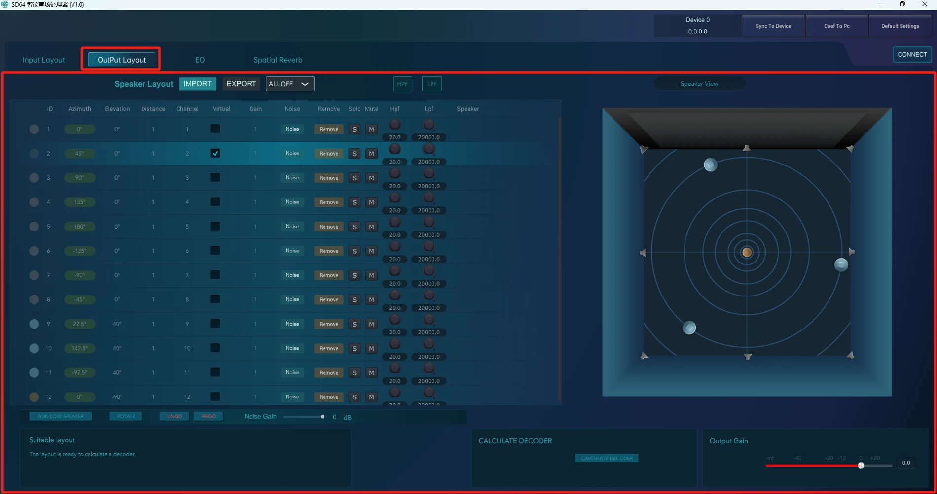
Input Layout describes the azimuth and elevation of each audio track.
Output Layout describes loudspeaker positions, distances and channels. Distance uses a fixed listening reference.
Calculate Decoder creates the decoder configuration; Sync To Device sends it to SD64. Continue with on-site verification.
From installation to parameters
Configure the installed loudspeakers instead of assuming a single room geometry. The software exposes azimuth, elevation, distance and output channel for the actual system design.
The listening reference defines distance; this illustration does not imply automatic listener tracking or show a measured acoustic result.
Describe sound as spatial objects and connect rendering to the actual loudspeaker layout.
Explore Next-Generation AudioConnect audio, metadata and creative context in one content workflow, beyond a standalone audio file.
Explore the NGA PlatformConnect audio algorithms, silicon, professional equipment and engineering tools. Support partners from technology integration to systems designed for real listening spaces.
NGA content platform, metadata format, SineKniter dev environment
Sound-field synthesis licensing, automated acoustic tuning, production-line automation
Dedicated audio processing and configurable signal paths
Participation in audio coding, rendering and metadata standards
Explore selected drafting contributions and granted invention examples in audio interfaces and network transport.
View representative workSee where rendering and sound-field technology are used in broadcast, performances and automotive audio.
Explore projectsSineMedia · Build what comes next